Basic Blocks and Flow Graphs
In this section, we are going to learn how to work with basic block and flow graphs in compiler design.
Basic Block
The basic block is a set of statements. The basic blocks do not have any in and out branches except entry and exit. It means the flow of control enters at the beginning and will leave at the end without any halt. The set of instructions of basic block executes in sequence.
Here, the first task is to partition a set of three-address code into the basic block. The new basic block always starts from the first instruction and keep adding instructions until a jump or a label is met. If no jumps or labels are found, the control will flow in sequence from one instruction to another.
The algorithm for the construction of basic blocks is given below:
Algorithm: Partitioning three-address code into basic blocks.
Input: The input for the basic blocks will be a sequence of three-address code.
Output: The output is a list of basic blocks with each three address statements in exactly one block.
METHOD: First, we will identify the leaders in the intermediate code. There are some rules for finding leaders, which are given below:
- The first instruction in the intermediate code will always be a leader.
- The instructions that target a conditional or unconditional jump statement are termed as a leader.
- Any instructions that are just after a conditional or unconditional jump statement will be a leader.
Each leader’s basic block will have all the instructions from the leader itself until the instruction, which is just before the starting of the next leader.
Example:
Consider the following source code for a 10 x 10 matrix to an identity matrix.
|
1
2
3
4
5
6
7
|
for i from 1 to 10 do
for j from 1 to 10 do
a [ i, j ] = 0.0;
for i from 1 to 10 do
a [ i,i ] = 1.0;
|
The three address code for the above source program is given below:
|
1
2
3
4
5
6
7
8
9
10
11
12
13
14
15
16
17
18
19
|
1) i = 1
2) j = 1
3) t1 = 10 * i
4) t2 = t1 + j
5) t3 = 8 * t2
6) t4 = t3 – 88
7) a[t4] = 0.0
8) j = j + 1
9) if j <= 10 goto (3)
10) i = i + 1
11) if i <= 10 goto (2)
12) i = 1
13) t5 = i – 1
14) t6 = 88 * t5
15) a[t6] = 1.0
16) i = i + 1
17) if i <= 10 goto (13)
|
- According to the given algorithm, instruction 1 is a leader.
- Instruction 2 is also a leader because this instruction is the target for instruction 11.
- Instruction 3 is also a leader because this instruction is the target for instruction 9.
- Instruction 10 is also a leader because it immediately follows the conditional goto statement.
- Similar to step 4, instruction 12 is also a leader.
- Instruction 13 is also a leader because this instruction is the target for instruction 17.
So there are six basic blocks for the above code, which are given below:
B1 for statement 1
B2 for statement 2
B3 for statement 3-9
B4 for statement 10-11
B5 for statement 12
B6 for statement 13-17.
Flow Graph
It is a directed graph. After partitioning an intermediate code into basic blocks, the flow of control among basic blocks is represented by a flow graph. An edge can flow from one block X to another block Y in such a case when the Y block’s first instruction immediately follows the X block’s last instruction. The following ways will describe the edge:
- There is a conditional or unconditional jump from the end of X to the starting of Y.
- Y immediately follows X in the original order of the three-address code, and X does not end in an unconditional jump.

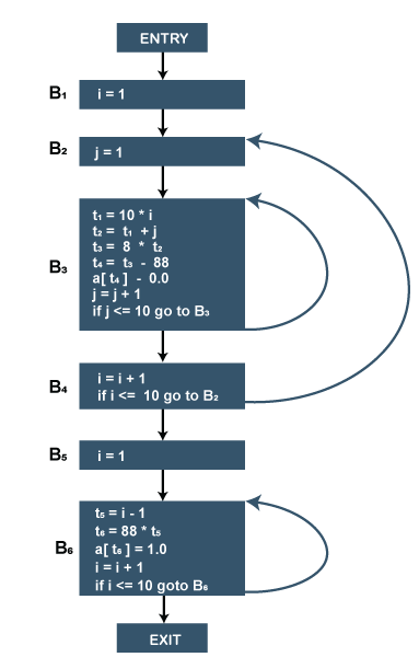
Flow graph for the 10 x 10 matrix to an identity matrix.
- Block B1 is the entry point for the flow graph because B1 contains starting instruction.
- B2 is the only successor of B1 because B1 doesn’t end with unconditional jumps, and the B2 block’s leader immediately follows the B1 block’s leader.
- B3 block has two successors. One is a block B3 itself because the first instruction of the B3 block is the target for the conditional jump in the last instruction of block B3. Another successor is block B4 due to conditional jump at the end of B3 block.
- B6 block is the exit point of the flow graph.


